
AI Fiber Monitoring: Catching Degradation Before It Becomes an Outage
How OTDR + machine learning shifts maintenance from reactive to predictive.
AI fiber monitoring is the practice of running an OTDR (optical time-domain reflectometer) against your fibers on a regular schedule, comparing every new trace with a stored "known good" baseline, and using machine learning to spot, classify and forecast the small changes that come before a fault. Instead of learning about a problem when customers call, the network operations center gets a prioritized alarm — with a distance to the fault — while the link is still carrying traffic.
Most fiber outages don't start as outages. A cable gets pinched behind a cabinet door, a splice slowly takes on moisture, a connector picks up dust during a patch change. Loss creeps up a fraction of a dB at a time until one day the optical budget runs out. Here's how to catch it on the way down.
What fiber degradation actually looks like
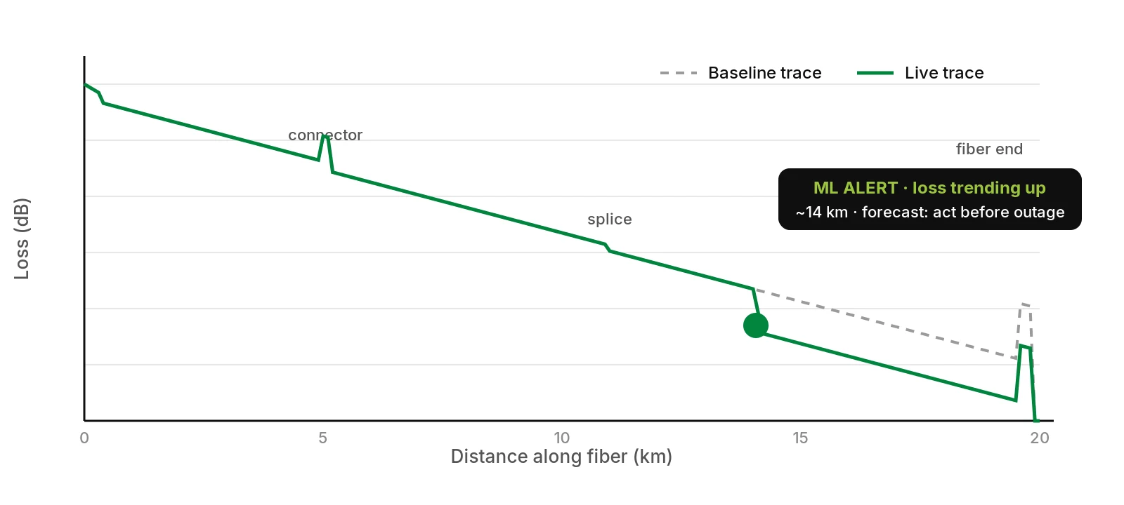
On an OTDR trace, healthy fiber is a straight, gently sloping line with predictable "events": a reflective spike at each connector, a small step at each fusion splice, and a large reflection at the fiber end. Degradation shows up as changes to that picture:
- Macrobends and microbends: a new loss step with no reflection, often where cable was re-routed, over-tied or crushed. Bend loss is wavelength-dependent — it is usually larger at 1550/1625 nm than at 1310 nm, which is a useful fingerprint.[1][2]
- Splice loss growth: an existing splice event that was 0.05 dB at commissioning and is now noticeably higher — typically mechanical stress or a failing splice tray.
- Connector contamination or damage: higher insertion loss and worse reflectance at a known connector location. Dirty end-faces are a well-known cause of optical problems in the field, which is why end-face inspection is standardized.[3]
- Water ingress: in closures and ducts, moisture and freezing cycles can stress fiber and raise loss — often at the same location, season after season.
- Aging and environmental drift: slow, distributed change along a span, correlated with temperature, construction activity or aerial cable movement.
None of these is a hard break on day one. Each is a trend — and trends are exactly what a computer is better at watching than a person is.
Traditional OTDR: powerful, but periodic
OTDR has been the fiber technician's core tool for decades.[4] The limitation is how it is usually used:
- Reactive: a tech brings a handheld OTDR after a link drops, shoots the fiber, finds the event and dispatches a splicing crew.
- Periodic: some operators re-shoot critical routes on a calendar, but between visits nobody is watching — and a manual trace comparison takes an experienced engineer.
Either way, the information that would have predicted the fault was there in the glass for days or weeks. Nobody was looking at it.
How machine learning reads an OTDR trace
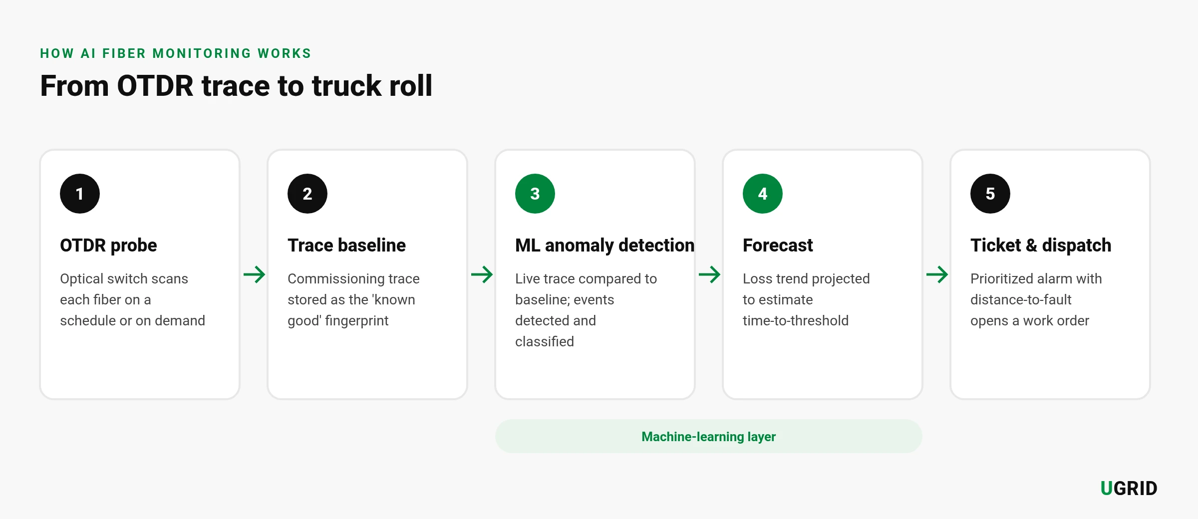
A remote fiber monitoring system puts an OTDR (usually with an optical switch, so one unit can scan many fibers)[5] in the central office or headend, and lets software do the watching. The ML layer typically does five jobs:
1. Baseline every fiber
At commissioning — or the first clean scan — the system stores a reference trace per fiber: every connector, splice and its loss and reflectance, plus the span attenuation. That fingerprint is what every future scan is judged against.
2. Detect anomalies against the baseline
Each new trace is aligned to the baseline and compared point by point. Instead of a single fixed threshold, the model learns how much each fiber normally varies (temperature, noise, measurement repeatability), so it can flag a real change without drowning the NOC in false alarms.
3. Classify the event
Trained on labeled traces, a classifier can suggest what kind of event it is seeing — a bend, a degrading splice, a dirty connector, a break — from the shape of the trace: reflective or not, step size, wavelength dependence, location relative to known events.[8][9]
4. Forecast the trend
This is where monitoring turns predictive. By fitting the loss history at a location over time, the system estimates when it will cross the link's alarm threshold — turning "this splice looks worse" into "this splice will need attention within weeks."
5. Prioritize the alarm
Not every event matters equally. Combining the forecast with what the fiber carries (a feeder serving hundreds of subscribers, a business circuit with an SLA, a dark spare), the system ranks alarms so the crew goes where the risk is highest first.
Reactive vs. preventive vs. predictive
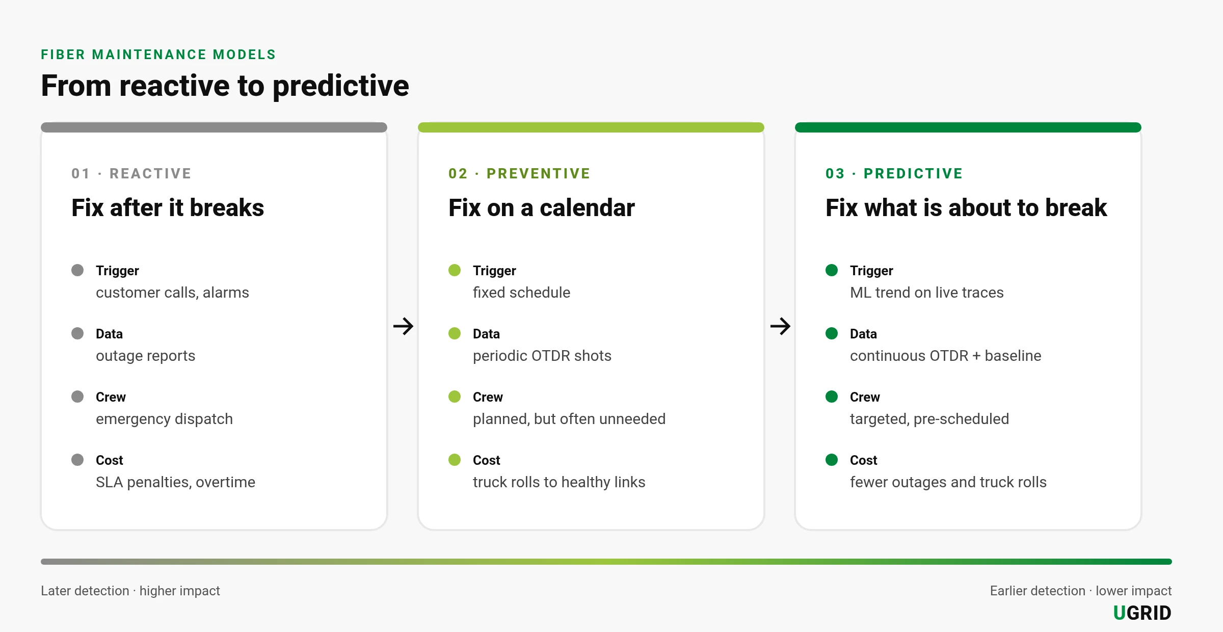
The three maintenance models differ in one thing above all: when you find out.
| Reactive | Preventive | Predictive (AI) | |
|---|---|---|---|
| Trigger | Outage, customer complaint | Calendar | Trend detected on live traces |
| Visibility between events | None | Snapshot at each visit | Continuous |
| Fault location | Found after dispatch | Found during visit | Distance-to-event in the alarm |
| Crew work | Emergency, after hours | Planned, sometimes on healthy links | Planned, targeted |
| Customer impact | Already happened | Reduced | Often avoided |
Rolling it out: practical steps for ISPs and MSOs
- Start where an outage hurts most. Feeder and backbone fibers, business/SLA circuits, and routes with a history of trouble. You don't need to monitor every drop on day one.
- Clean up the baseline. Garbage in, garbage out: clean and inspect connectors, then take baseline traces on known-good fibers. Record the route against GIS/as-built data so a distance on the trace maps to a manhole or pole.
- Choose in-service or dark-fiber testing. Monitoring a live PON or lit link needs an out-of-band test wavelength (commonly 1625 or 1650 nm)[6][7] with WDM couplers and filters so the OTDR doesn't disturb traffic. Dark spare fibers in the same cable are a simpler starting point.
- Tune alarms before trusting them. Run in "observe" mode for a few weeks, review what the model flags with your field team, and set thresholds per route class.
- Close the loop with operations. Push alarms into the ticketing/OSS system you already use, and feed technicians' findings ("dirty connector at ODF 3", "crushed duct at 4.2 km") back as labels. The classifier gets better with every repair.
What to measure
Predictive maintenance should pay for itself in numbers your operations team already tracks. Measure before and after rollout, on the same routes:
- MTTR (mean time to repair): distance-to-fault in the alarm shortens the "find it" part of every repair.
- Outage minutes and customers affected: faults fixed before they drop service never show up here at all.
- Truck rolls: fewer exploratory and repeat dispatches; more single-visit fixes.
- Emergency vs. planned work ratio: the clearest sign you've moved from reactive to predictive.
- SLA compliance and credits: especially for business and wholesale circuits.
- Alarm precision: the share of alarms that led to a real finding. If it is low, crews will stop trusting the system — track it from day one.
Bottom line
An OTDR already sees fiber degradation long before customers do. Adding a baseline, continuous scanning and machine learning simply makes sure someone is looking — and turns a trace into a ranked, located, forecasted work order. The fault still gets fixed; it just gets fixed on your schedule instead of the outage's.
Remote fiber testing with AI degradation forecasting
The UGrid uFT Intelligent Remote Fiber Testing System combines OTDR-based real-time fiber fault detection and smart alerts with AI degradation forecasting, to help cut downtime and repair cost.
See the uFT-2U Product Page →References
- ITU-T Recommendation G.652, Characteristics of a single-mode optical fibre and cable. https://www.itu.int/rec/T-REC-G.652
- ITU-T Recommendation G.657, Characteristics of a bending-loss insensitive single-mode optical fibre and cable. https://www.itu.int/rec/T-REC-G.657
- IEC 61300-3-35:2022, Visual inspection of fibre optic connectors and fibre-stub transceivers. https://webstore.iec.ch/en/publication/64254
- IEC 61746-1:2009, Calibration of optical time-domain reflectometers (OTDR) — Part 1: OTDR for single mode fibres. https://webstore.iec.ch/en/publication/5748
- ITU-T Recommendation L.302 (formerly L.40), Optical fibre outside plant maintenance support, monitoring and testing system. https://www.itu.int/rec/T-REC-L.302
- ITU-T Recommendation L.41, Maintenance wavelength on fibres carrying signals. https://www.itu.int/rec/T-REC-L.41
- ITU-T Recommendation L.313 (formerly L.66), Optical fibre cable maintenance criteria for in-service fibre testing in access networks. https://www.itu.int/rec/T-REC-L.313
- K. Abdelli, J. Y. Cho, C. Tropschug, “ML-based Anomaly Detection in Optical Fiber Monitoring,” arXiv:2202.11756 (2022). https://arxiv.org/abs/2202.11756
- “ML approaches for OTDR diagnoses in passive optical networks — event detection and classification,” Journal of Optical Communications and Networking (Optica). https://doi.org/10.1364/jocn.516659