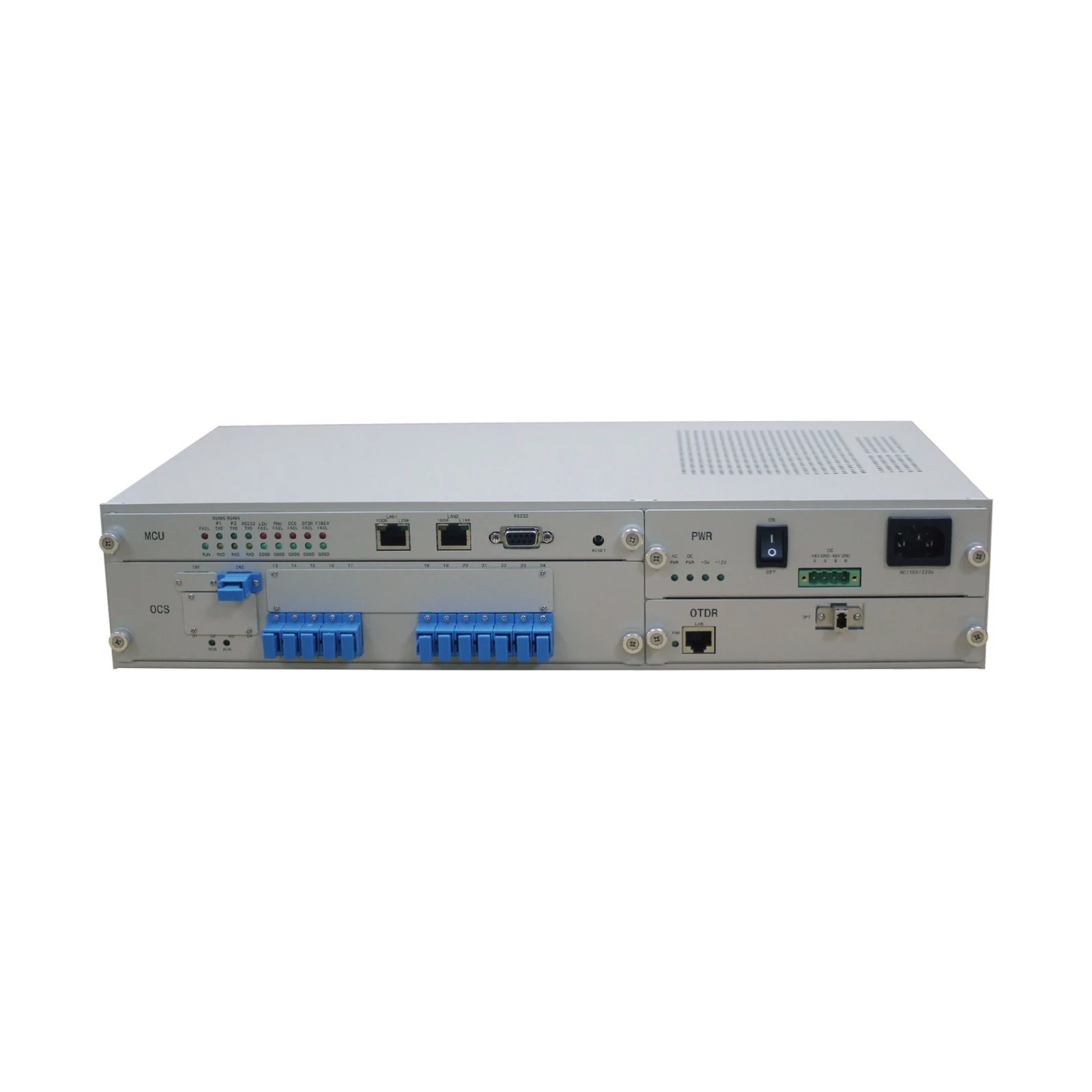
The uFT-2U is an intelligent remote fiber test system (iRFTS) — a centralized, OTDR-based platform that monitors dark fiber, live fiber and PON networks 24/7, detects faults the moment received power drops, pinpoints the bend or break automatically, and shows the breakage point on the map.
A light source and power detector watch every monitored fiber around the clock — testing is built into the Remote Test Unit and runs fully automatically, with no technician dispatch.
When the power detector sees a loss or drop in received power, it raises a fiber alarm and triggers the OTDR to scan the fiber and identify the bend or failure point.
One system for dark fiber, live in-service fiber and PON networks, with centralized control and fiber network administration — including cable commissioning and SLA reporting.
Online or offline maps down to street level show exactly where a fault sits. Staff work from PC and mobile devices, and OTDR ghost traces are filtered automatically.
A microprocessor-based main control unit replaces a separate industrial PC, cutting power consumption for ESG goals while keeping the system stable and easy to expand.
Forecast and historical fiber reports support SLA fiber subscribers and fiber degradation planning. Cascaded shelves grow system capacity with your needs.
The uFT-2U Remote Test Unit sits in the central office under centralized FMS control. One fiber core on each path is monitored continuously — in point-to-point links and ring routes alike.
Centralized control — dark fiber · live fiber · PON networks · point-to-point links · ring routes
The light source (LSU) emits light continuously, 24/7, and the power detector (PMU) continuously checks the received power level on every monitored fiber.
A loss or decrease of received power is detected the moment it happens and raised as a fiber alarm — no waiting for customer reports or scheduled OTDR sweeps.
The OTDR is triggered automatically to scan the fiber and identify the bend or failure point, so repair crews go straight to the fault and service downtime shrinks.
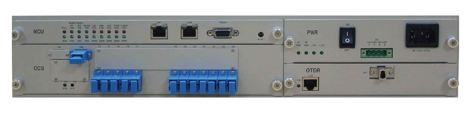
The production uFT-2U front panel: MCU and power modules on the top row, the OCS optical switch and OTDR module below — every control and port labeled on the unit itself.
 1
2
3
6
4
5
Two reference deployments from the uFT-2U datasheet — the same monitor · detect · locate sequence protects a single span or a closed ring.
The LSU at the remote site emits light continuously (24/7) to the PMU at the central office. When the PMU detects a loss or decrease of received power, the OTDR is triggered to scan the fiber and identify the bend or failure point.
One fiber core on each path is connected into a ring loop (A → B → C → D → A). The LSU emits light continuously around the loop to the PMU; a detected loss triggers the OTDR scan that locates the fault on the ring.
Online or offline maps down to street level, from PC and mobile devices — faults appear where they are, not as raw trace coordinates.
The FMS runs on an on-premises server, or as a virtual machine in a private cloud — the same centralized control either way.
Forecast and historical fiber reports for SLA fiber subscribers, built from the system's continuous test history.
An open API, with northbound system integration commands and protocols available on request.
Every value below is from the official uFT-2U datasheet (Rev. 01).
| Chassis & power | |
| Form factor | Stand-alone 2U chassis; 19-inch or 23-inch rack mount |
|---|---|
| Open slots | Power supply, MCU, OTDR and OCS modules |
| Optional modules | LSU, PMU and WDM, installed in a separate 2U chassis |
| Operating temperature | 0 to 50 °C |
| Weight | < 10 kg |
| Power supply | DC −36 to −72 V DC; AC 110 to 220 V AC, 50/60 Hz ± 5% |
| Maximum output | 50 W |
| LED indicators (power) | AC PWR, DC PWR, +5V, +12V |
| MCU module | |
| Memory / storage | 512 k or higher / 24 MB or higher |
| Interfaces | 2 × 10/100 Ethernet (LAN1, LAN2), RS-232 console, 2 × RS-485 |
| System maintenance | Watchdog self-diagnostic |
| LED indicators | RUN / FAIL; RS-485 #1, RS-485 #2 and RS-232 TXD / RXD; LSU, PMU, OCS, OTDR and FIBER GOOD / FAIL; LAN 100M / LINK |
| System protocols | Northbound system integration commands and protocols on request |
| OTDR module | |
| Operating wavelength | 1550 nm or 1625 nm (± 20 nm) |
| Dynamic range | 30 to 45 dB |
| X-axis (distance) resolution | ≤ 25 cm |
| Y-axis resolution | ≤ 0.001 dB |
| Refractive index | 1.2000 to 1.6000, 0.0001 step |
| Accuracy | ±(1 m + 3 × 10⁻⁵ × distance + sampling resolution) |
| Pulse widths | At least 5: 3 ns, 5 ns, 10–100 ns, 200–500 ns, 1–5 µs, 10–20 µs |
| Max. sampling points | 256,000 |
| OCS module (optical switch) | |
| Capacity | 4 / 8 / 12 / 16 ports |
| Switching time | ≤ 300 ms |
| Passband | ±20 nm @ 1550 nm / 1625 nm |
| Return loss | ≥ 45 dB |
| Insertion loss | ≤ 1.5 dB |
| Crosstalk | ≤ −70 dB |
| Repeatability | ≤ 0.1 dB |
| Lifetime | 10 million switching cycles |
| Optical interface | SC/PC, SC/APC or LC/PC |
| LED indicators | RUN, ALM |
| Optional modules | |
| LSU (light source) | 1550 nm; 2 laser sources; output power ≥ −7 dBm @ 4 ports; stability ≤ 0.3 dB (25 °C, 24 h) |
| PMU (power detector) | 1280 to 1655 nm; +5 to −65 dBm (dark fiber), +15 to −40 dBm (live fiber); accuracy ≤ 0.5 dB; resolution ≤ 0.1 dB |
| WDM | 1310 nm & 1550 nm / 1625 nm; directivity ≥ 50 dB; isolation ≥ 30 dB; insertion loss ≤ 1.5 dB |
Intelligent OTDR-based remote fiber test system in a stand-alone 2U chassis. Specify the configuration below when ordering — contact UGrid Network Inc. to confirm the full part number.
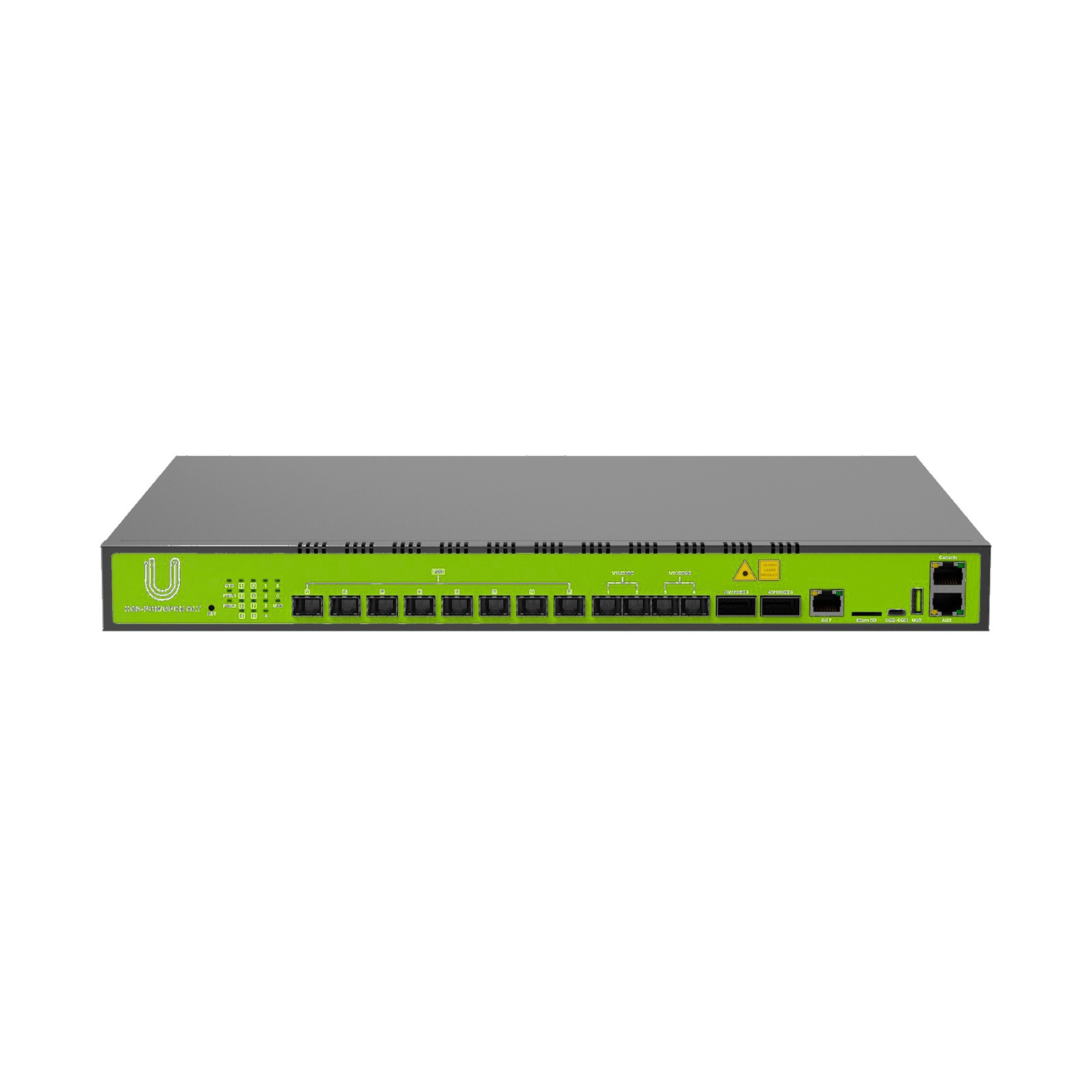
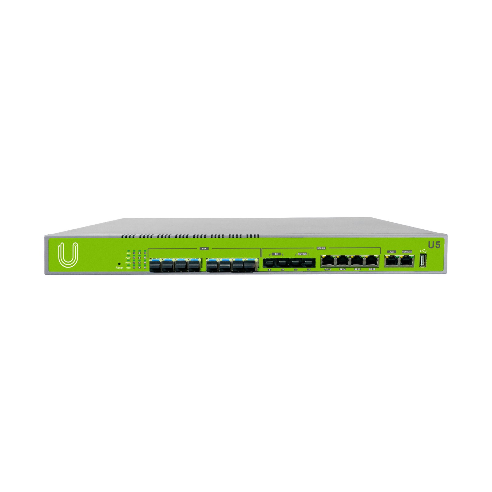
A remote fiber test system centralizes fiber testing in remote test units (RTUs) installed in central offices. The uFT-2U's embedded MCU runs automatic OTDR testing under central control, so operators administer dark fiber, live fiber and PON networks — monitoring, fault detection and cable commissioning — from one fiber management system instead of dispatching technicians with handheld OTDRs.
A light source unit (LSU) emits light continuously, 24/7, while a power detector (PMU) watches the received power level. When it sees a loss or drop, the system raises a fiber alarm and triggers the OTDR to scan the fiber and identify the bend or failure point, with distance resolution of 25 cm or better — the fault is then shown in the web-based GIS interface, down to street level.
Dark fiber, live (in-service) fiber and PON networks, in point-to-point links and ring routes. One system covers all three, with centralized control and fiber network administration.
The OTDR module works at 1550 nm or 1625 nm with a 30 to 45 dB dynamic range, distance (X-axis) resolution of 25 cm or better, up to 256,000 sampling points and at least five pulse widths from 3 ns to 20 µs. The optical switch (OCS) connects 4, 8, 12 or 16 ports with switching times of 300 ms or less.
The uFT-2U is a stand-alone 2U chassis for 19-inch or 23-inch racks, and shelves can be cascaded to grow capacity. The fiber management system (FMS) runs on an on-premises server or a virtual machine in a private cloud, and staff access the web GIS interface from PC and mobile devices. An open API provides northbound integration commands and protocols on request.
Tell us about your fiber plant — our team typically responds within 2 business days.
Request a Quote